Enhanced Monitoring for Critical Fiber Connections

Ethernet’s Role in Control System Advancements
Ethernet networks serve as the fundamental infrastructure for facilitating Internet Protocol (IP) communications. While the inception of Ethernet dates back to 1973, when the original concept underwent testing at Xerox's Palo Alto Labs, its practical utility in systems and device applications has only recently gained momentum. The progression of advanced switching technology has rendered Ethernet networks increasingly relevant in control systems, encompassing domains such as traffic management and transportation systems.
In innovation, our efforts have led to the augmentation of Ethernet switches through the integration of Digital Diagnostics & Monitoring functionality into the fiber optic ports of these switches. This innovative feature empowers users to assess optical parameters at designated switches, thereby ascertaining the performance not only of the switches themselves but also of the optical fiber infrastructure. This tool proves invaluable for diagnosing anomalies within the fiber optic cable infrastructure, enabling remote troubleshooting from the convenience of the management center, thus preventing the need for physical interventions and on-site visits.
Switching Technology Up Close
Ethernet operates as per the IEEE 802.3 standard, encompassing media types like wire, fiber optics, and wireless, alongside electrical characteristics and addressing schemes for networking.
Designed for computer-to-computer communications, Ethernet functions as a packet-based communication technology. It envisions each device connected to the same wire, much like a group of people in a room. When a device wishes to communicate, it listens, talks if the wire is clear, and backs off if multiple devices communicate simultaneously.
Modern Ethernet networks employ switches for full duplex communication over various mediums like twisted pair, fiber optic, or wireless channels. This eliminates simultaneous transmissions on the same wire, revolutionizing network dynamics beyond previous constraints.
Every Ethernet interface receives a unique hardware address at production. Switches use this address to facilitate connections.
To learn about a product's manufacturer, the associated MAC address can be checked here.
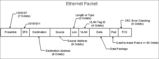
When transmitting data via Ethernet, a device encapsulates the information into a packet of binary digits (bits) from the sender's MAC address to the recipient's MAC address. The core function of an Ethernet switch involves constructing a comprehensive reference table that cross-links MAC addresses with corresponding ports to which devices are linked. Upon receiving a packet, the Ethernet switch evaluates the destination MAC address, locates a corresponding entry in its reference table, and consequently directs the packet to the port associated with that particular device. In the event of an absence of a matching entry in the table, the switch disseminates the packet across all ports at the same time.
Over time, advancements in switching technology have propelled Ethernet into the
practicability as a network technology within real-time control networks, as exemplified by traffic signal systems. Given the geographical dispersion of traffic signals, a network that interconnects traffic control cabinets with a central hub comprises switches deployed at varying distances, commonly interconnected via fiber optic cables. This configuration introduces a distinct array of challenges, encompassing the assurance of robust network integrity and the development of effective troubleshooting methodologies.
Fiber Optic Gaps
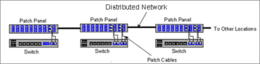
Distributed networks, such as Traffic Signal Networks or Highway Management Networks, pose a unique challenge due to the considerable distance between Ethernet switches, sometimes spanning miles apart from each other and from the central control center. In cases where fiber optic cables are utilized, the connectivity typically adheres to the following design concept.
However, the fiber optic cable infrastructure is susceptible to disconnections and damage stemming from various sources. Issues can arise from misconnections involving patch panels and patch cables, including incorrect fiber types, as well as potentially faulty splices. Moreover, the risk of incidents like "backhoe fade" persists, wherein new excavation work inadvertently severs the fiber optic cables. Rectifying problems within the fiber optic cable infrastructure demands a complex troubleshooting process, necessitating specialized equipment and expertise to pinpoint the root cause of issues that may lead to light attenuation.
Long-Distance Connectivity Solution
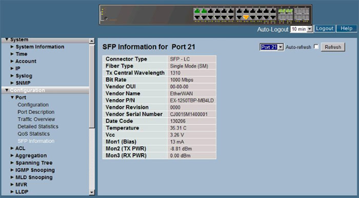
EtherWAN has developed an Ethernet switch with integrated optical diagnostics, known as Digital Diagnostics Monitoring (DDM) / Digital Optical Monitoring (DOM), which empowers users to utilize the Ethernet switch's management functions for resolving fiber optic connectivity issues.
Accessible through the switch management interface, including web browsers, telnet, and the console port, the DDM/DOM subsystem provides users with access to critical information for any switch within the network, regardless of their location.
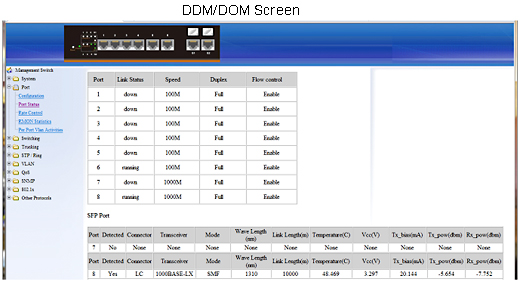
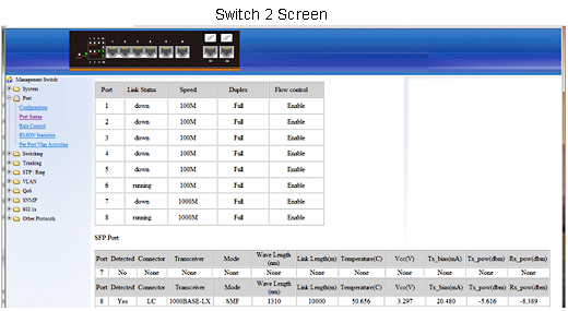
Found within the port status screen, the DDM/DOM interface displays the SFP port(s) status. In the example, port 7 lacks a module, while port 8 is equipped with one. DDM/DOM effectively measures and tracks the operational parameters of the SFP module, encompassing optical characteristics, presenting users with a comprehensive set of data to assess the Laser's health and the overall performance of the fiber optic cable infrastructure.
In the displayed screen, the SFP module's characteristics are showcased using DDM/DOM, highlighting its transmission wavelength of 1310nm and its suitability for distances up to 10km.
► The following parameters are measured by the DDM/DOM subsystem:
- Temperature inside the SFP Module.
- Vcc
- Voltage supply to the SFP.
- Tx Bias
- Current to the Laser Diode Transmitter.
- Tx Power
- The amount of light being transmitted into the fiber optic cable represents a measured value; however, it may not reflect the actual power entering the cable, as it doesn't consider the condition of the actual cable. This number can be used as a reference to monitor the health of the laser.
- Rx Power
- The amount of light being received from the fiber optic cable.
The primary parameters include Tx Bias, Tx Power, and Rx Power. Monitoring Tx Bias provides insights into the aging of the Laser component, particularly in comparison to others within the network, facilitating proactive maintenance. This approach empowers users to engage in preventive measures. By determining the Tx power at one end of the fiber cable and correlating it with the Rx power at the connected switch, users can assess attenuation and identify potential anomalies in the optical path, thereby ensuring optimal cable plant performance. Consistently tracking these measurements aids in identifying deteriorating optical interfaces or path conditions, enabling users to take proactive steps. The convenience of conducting these assessments from the control room, even over a live network, encourages users to monitor these parameters. This proactive approach is more likely to be adopted, allowing users to ensure network health rather than reacting to issues after they have already occurred.
Fiber Optic Management Benefits
Example of a live network between two switches:
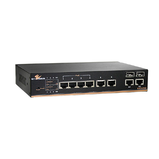
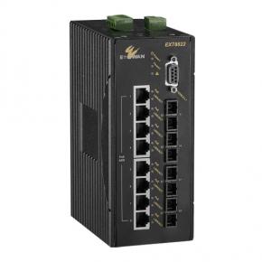
► EX74000/EX78000
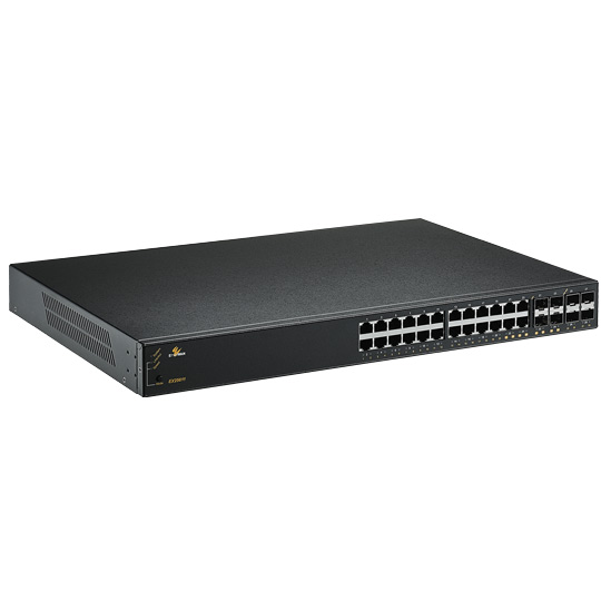
►EX25611
There is a minor power reduction when connected with a short jumper cable. We focus on these two parameters because they are the most useful indicators in troubleshooting issues.
See the screens below for an example of what happens when one of the fiber optic connectors is not seated completely.
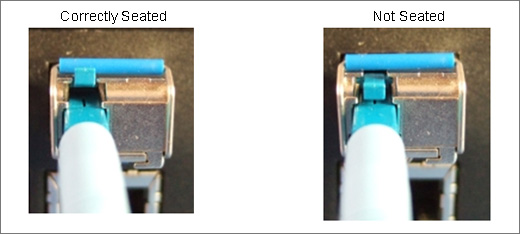
It is challenging to detect the issue via physical inspections. However, the screen below shows the difference in receiving power from the normal SW 2 screen, shown above. The RX power level went from -8.389 dBm to -22.366 dBm or 13.977 dB reduction of optical power. The problem would remain unnoticed with conventional equipment lacking the DDM feature. However, it's only a matter of time until factors like cable weight or vibrations may lead to disconnection, resulting in network downtime.
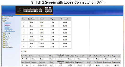
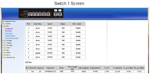
Observe the RX power level at -22.366 dBm, which falls significantly below the expected range. Consequently, we can promptly investigate the transmitting switch and assess whether the TX power level is within the normal parameters.
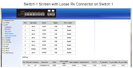
In this scenario, it's reasonable to suspect an issue between Switch 1 and Switch 2, even if the TX power is normal (-8.392). To troubleshoot, the connection must be inspected. A loose connector on Switch 1, responsible for transmitting to Switch 2, is securely connected. This issue can stem from a defective patch cable, improper connector termination, or an inadequate splice.
► Benefits of DDM/DOM:
Ethernet switches with DDM/DOM allow users of distributed networks that utilize fiber optic cable to be more proactive in maintaining their network using the standard optical interfaces. The results are fewer truck rolls, less network downtime, less investment in equipment and training, and smoother operation.
Related products:
EtherWAN – " When Connectivity is Crucial "
► For more information, please contact: info@etherwan.com.tw


