Enhanced Monitoring for Critical Fiber Connections

Overview
Ethernet networks are the transport mechanism for Internet Protocol (IP) communications. Although Ethernet has been around since 1973 when the original concept was tested at Xerox's Palo Alto Labs, it has just in the last few years become viable in control system applications and even more recently in CCTV applications. The invention and development of better switching technology has made Ethernet networks more applicable to control system networks, such as traffic and transportation systems.
We have enhanced Ethernet switches by adding a Digital Diagnostics & Monitoring function to the fiber optic ports of the switch. This function allows a user to measure optical parameters at a specific switch and determine performance levels of not only the switch but the optical fiber plant as well. This is an indispensible tool when used to trouble shoot fiber optic cable plant anomalies from the comfort of the management center, rather than rolling a truck to various cabinets.
Technology
Ethernet is a technology that is defined by IEEE 802.3 standard. This standard defines the types of media, wire, fiber optics and wireless, the electrical characteristics and the addressing scheme for an Ethernet network.
Ethernet is a packet communications technology, designed for computer to computer communications. The rules concerning Ethernet communications assumes every machine is connected to the same piece of wire, much like a meeting of a group of people in one room. If a machine wants to communicate (talk) it listens and if there is nothing on the wire it talks. If two machines talk at the same time they hear each other so they back off and wait a random time period then try again.
Today's Ethernet networks use switches to create a network and every device is communicating on a full duplex connection, over Twisted pair wire, fiber optic cable or wireless channels, so there are never two machines sending at the same time, on the same piece of wire. This changes the dynamic of how the network operates and allows Ethernet networks to go where they could not go before the development of switches.
Every Ethernet interface device is assigned a unique hardware address when it is manufactured. This address is used by switches to determine how to connect machines to each other. You can go to the following URL and lookup a MAC address if you want to know who manufactured a product.
http://standards.ieee.org/regauth/oui/index.shtml
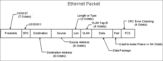
When a machine sends information via Ethernet it sends a packet of bits with the sending machine's MAC address and the destination machines MAC address. The main job of an Ethernet switch is to create a reference table that cross references a machine's MAC address and the Port where that machine is connected. When a packet enters an Ethernet switch the switch looks at the destination MAC address finds the match in it's table and forwards that packet to the port where that machine is connected. If there is not a match in the table then it forwards that packet to all ports at the same time.
As switching technology has improved Ethernet has become a viable network technology for use in real time control networks, such as traffic signals. Since, by nature, traffic signals are geographically separated from each other a system that networks traffic cabinets to a central location is comprised of switches that are separated by distance and generally connected by fiber optic cable. This can present a new set of challenges in insuring good network integrity and troubleshooting techniques.
Challenges
Distributed networks, such as Traffic Signal Networks or Highway Management Networks present a special challenge because the location of Ethernet switches is sometimes miles apart from each other and miles from the central control center. When a network uses fiber optic cable the connectivity generally follows the concept shown below.
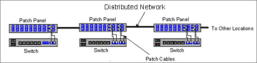
The fiber optic cable plant is vulnerable to disconnects and damage from various sources. There are patch panels and patch cables that can be connected with the wrong type of fiber and/or misconnected and there are splices that can become faulty. Then there is always the possible of "backhoe fade" when a new dig simply cuts through the fiber optic cable. Trouble shooting the fiber optic cable plant can be challenging and require specialized equipment and expertise to find the source of a problem that may be causing light attenuation.
Solution
EtherWAN Systems has developed a Ethernet switch with optical diagnostics built in, called Digital Diagnostics Monitoring (DDM) / Digital Optical Monitoring (DOM). Using DDM/DOM a user can use the Ethernet switch management functions to trouble shoot fiber optic connectivity issues.
The DDM/DOM subsystem is available through the switch management screens. Whether using a web browser, telnet or the console port, a user can access this information for any switch in the network from any location on the network.
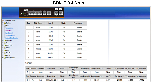
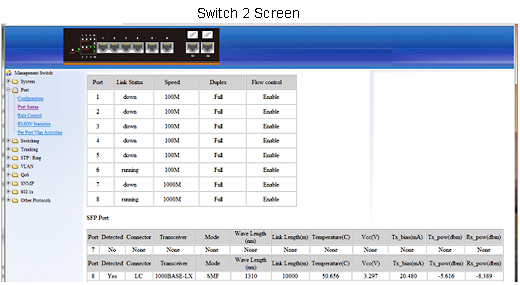
The DDM/DOM screen is part of the port status screen. It shows the status of the SFP port(s), in the screen shown above this switch does not have a module plugged into port 7 but does have a module in port 8. DDM/DOM measures and monitors the operating parameters of the SFP module, including the optical characteristics and displays a set of parameters that allow users to determine the health of the Laser as well as the performance of the fiber optic cable plant.
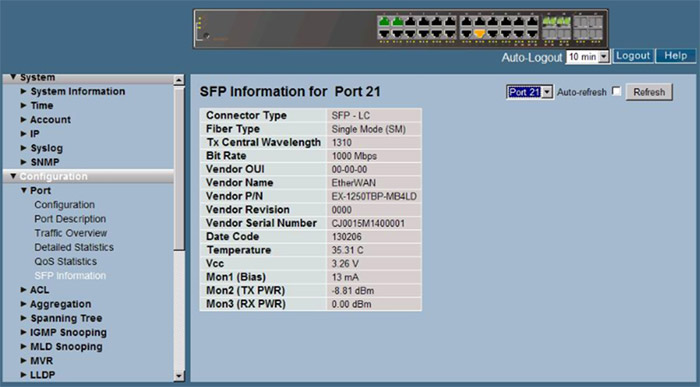
The screen, shown above, shows the characteristics of an SFP module using DDM/DOM. Notice the particular device shown transmits at 1310nm and is designed for a maximum of 10km.
► The following parameters are measured by the DDM/DOM subsystem:
- Temperature inside the SFP Module.
- Vcc
- Voltage supply to the SFP.
- Tx Bias
- Current to the Laser Diode Transmitter.
- Tx Power
- The amount of light being transmitted into the fiber optic cable. This is a measured value but it may not reflect the actual power entering the cable, it doesn't consider the condition of the actual cable. This number can be used as a reference to monitor the health of the laser.
- Rx Power
- The amount of light being received from the fiber optic cable.
Results
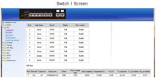
Example of a live network between two switches:
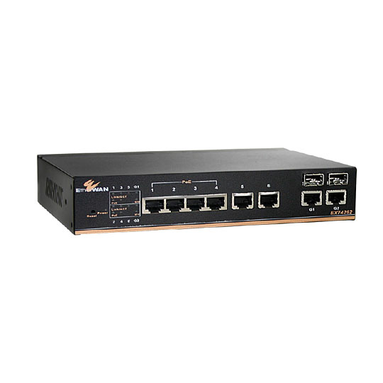
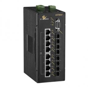
► EX74000/EX78000
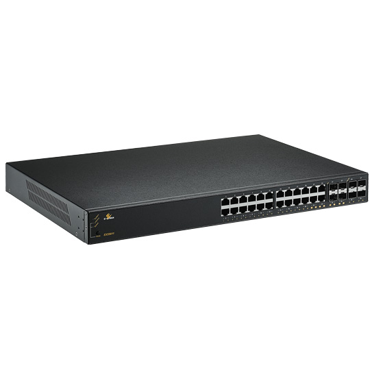
►EX25611
Notice the power levels between the switches. Switch 1 TX power is -8.392 dBm and Switch 2 RX power is -8.389 dBm. Switch 2 TX power = -5.616 dBm and Switch 1 RX = -5.017 dBm. There is a small loss of power when connected with a short jumper cable. We focus on these two parameters because these are the most useful in trouble shooting problems with the fiber optic plant.
See the screens below for an example of what happens when one of the fiber optic connectors is not seated completely.
What happens if one of the connectors is not seated correctly? The two pictures below show the physical difference between an LC connector that is seated correctly and one that has not been pressed in until the lock clicks in place.
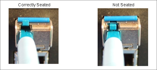
There is not much physical difference, it would certainly be difficult to catch this anomaly during a routine physical inspection. However, as the screen below shows the difference in receive power from the normal SW 2 screen, shown above. The RX power level went from -8.389 dBm to -22.366 dBm or 13.977 dB loss of optical power. The network is working fine, this anomaly would not be discovered using a normal set of equipment without the DDM feature, until one day the weight of the cable and/or vibration caused the connector to move farther out or disconnect completely and the network goes down.
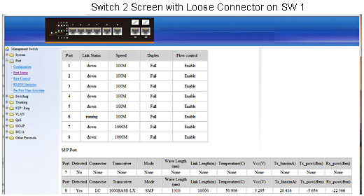
Notice the RX power level at -22.366 dBm, is well below what we would expect so we can immediately look back at the switch that is transmitting to this one and determine if the TX power level is normal.
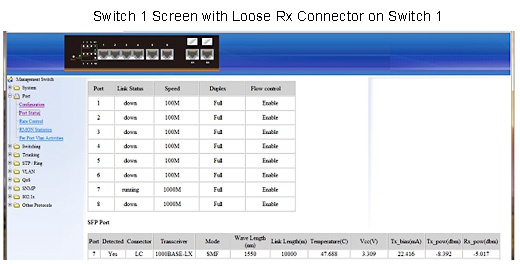
Switch 1 has TX power = -8.392 dBm so it is normal. In this case we can assume there is some anomaly between Switch 1 and Switch 2. Starting with the obvious we check the connections. In this case we find a loose connector on Switch 1 that is transmitting to Switch 2, this connector is not seated correctly. It could have been a bad patch cable or bad connector termination or bad splice.
► Benefits of DDM/DOM:
Ethernet switches with DDM/DOM allow users of distributed networks that utilize fiber optic cable to be more proactive in maintaining their network using the than standard optical interfaces. The results are fewer truck rolls, less network down time, less investment in equipment and training and smoother operation.
Related products:
EtherWAN – " When Connectivity is Crucial "
► For more information, please contact: info@etherwan.com.tw


