How does the power fault alarm relay operate?
Answer:
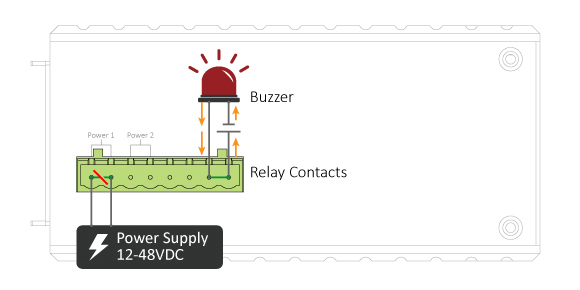
Following are the two circuit diagrams that explain the relay operation. The first diagram demonstrates the red contact is normally open under a normal operating condition, meaning that the 12-48VDC Power Supply constantly delivers power to the switch without any power failure. "Normally" refers to a de-energized condition of the red contact as there is no magnetic force around the copper coil.

The second diagram demonstrates that the 12-48VDC Power Supply has somehow malfunctioned, resulting in a power cut. Therefore, a current flows through circuit (A) and the copper coil generates a magnetic force that attracts the red contact and forms a closed circuit (B). The buzzer starts to make a loud sound due to the power failure event.