What is the PoE power pins assignment mode A & B?
Answer:
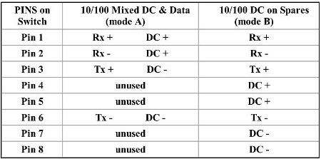
There are two modes of PoE, A and B. Mode A delivers power on the data pairs of 100BASE-TX or 10BASE-T. Mode B delivers power on the spare pairs. PoE can also be used on 1000BASE-T Ethernet, in which case there are no spare pairs and all power is delivered using the phantom technique.
In mode A, pins 1 and 2 form one side of the 48 VDC, and pins 3 and 6 form the other side. These are the same two pairs used for data transmission in 10BASE-T and 100BASE-TX, allowing the provision of both power and data over only two pairs in such networks. The free polarity allows PoE to accommodate for crossover cables, patch cables and auto-MDIX.
In mode B, pins 4–5 form one side of the DC supply and pins 7–8 provide the return; these are the "spare" pairs in 10BASE-T and 100BASE-TX. Mode B, therefore, requires a 4-pair cable.
The PSE (power sourcing equipment), not the PD (powered device), decides whether power mode A or B shall be used. PDs that implement only Mode A or Mode B are disallowed by the standard.
Updated in September 2017
| Mode A | Mode B | |
| ER52000 | V | |
| ER58000 | V | |
| ER59000 | V | |
| EX74000 | V | |
| EX75000 | V | |
| EX76000 | V | |
| EX78000 | V | V |
| EX78602 | V Port 5, 6 | V Port 1~6 |
| EX78162 | V | |
| EX78900 | V | V |
| EX34000 | V | |
| EX45900 | V | |
| EX42300 | V | |
| EX38000 | V | |
| EX45000 | V | |
| EX46900A | V | |
| EX46100 | V | |
| EX48000 | V | |
| EX48000A | V | |
| EX49000 | V | |
| EX49000A | V | |
| EX17008 | V | |
| EX17016 | V | |
| EX17082 | V | |
| X17162 | ||
| X17242 | ||
| X17908 | V (Port 2,4,6,8) | V (Port 1,3,5,7) |
| EX17044A | V | |
| EX17008A | V | |
| EX17016A | V | |
| EX17082A | V | |
| EX17162A | V | |
| EX17908A | V (Port 2,4,6,8) | V (Port 1,3,5,7) |
| EX24402 | V | |
| EX26182 | V | |
| EX26262 | V |


